Note
This technote is not yet published.
Fibers deployed at the Summit
1 Introduction
The purpose of this document is to provide information related to the installation, materials used, network point areas, and the number of fiber filaments used per floor. This documentation also reflects how the physical network of the main building is built by putting an emphasis on the fact that the project is still undergoing construction and will undergo continuous changes in the near future. These changes include additional network points or removing those that are already in place. The materials used for this project were all selected based on their quality and technical properties so that the project can operate at maximum performance in the operations phase.
2 Current Deployment
2.1 Materials Used
2.1.1 Fiber:
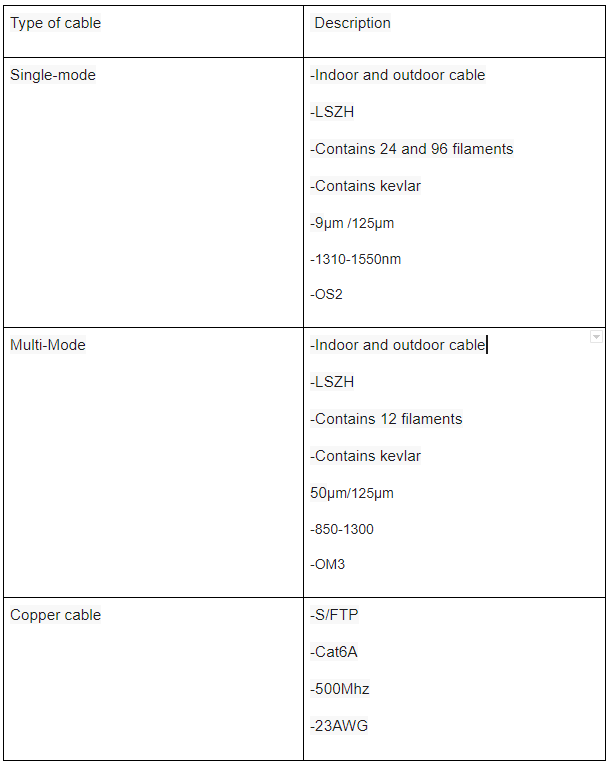
Single-mode fiber was selected and installed due to its technical properties hence it provides an unlimited transmission limit. This fiber will only be used for the equipment that functions as a transmitter (TX) and receiver (RX).
In some occasions, multi-mode fiber cable connections will be set up and installed for any technical equipment that requires it.
2.1.2 Copper:
It is also noted that UTP S/FTP cables were also selected due to the cable properties and ability to work at 10GBASE-T speeds. All network points were installed with this type of cable, both the access points and telephony connection systems. In regard to end-user devices, UTP CAT6 was setup.
2.1.3 Component Features
3 Areas of interest
- First floor
- Second floor
- Third floor
- Fourth floor
- Fifth floor
3.1 First Floor
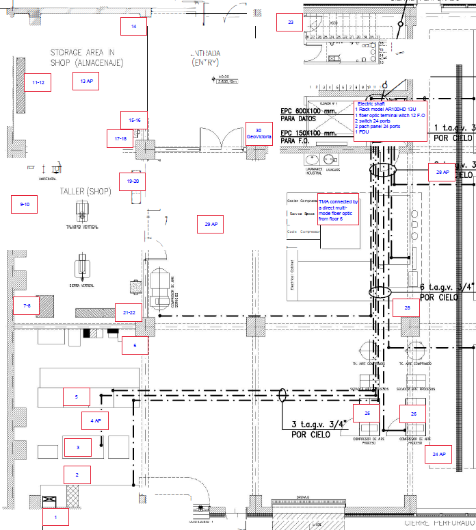
The first floor is made up of the following elements.
First Floor:
- 30 Network points in total
- 5 Access points
- 4 Boxed VoIP
- 2 24-port patch panel with modular jack, category 6A, 4 pairs
- 1 Optic header with 12 SM OS2 optical fibers and LC Full-Duplex UPC connectors
- 2 24-port switch
- 1 13U wall rack
3.1.1 First Floor Image
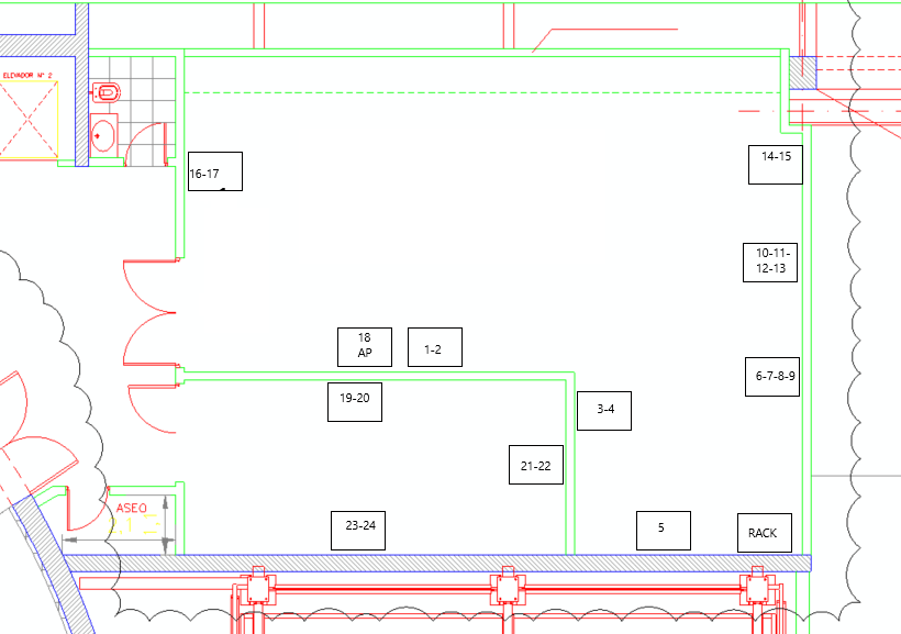
3.2 Second Floor
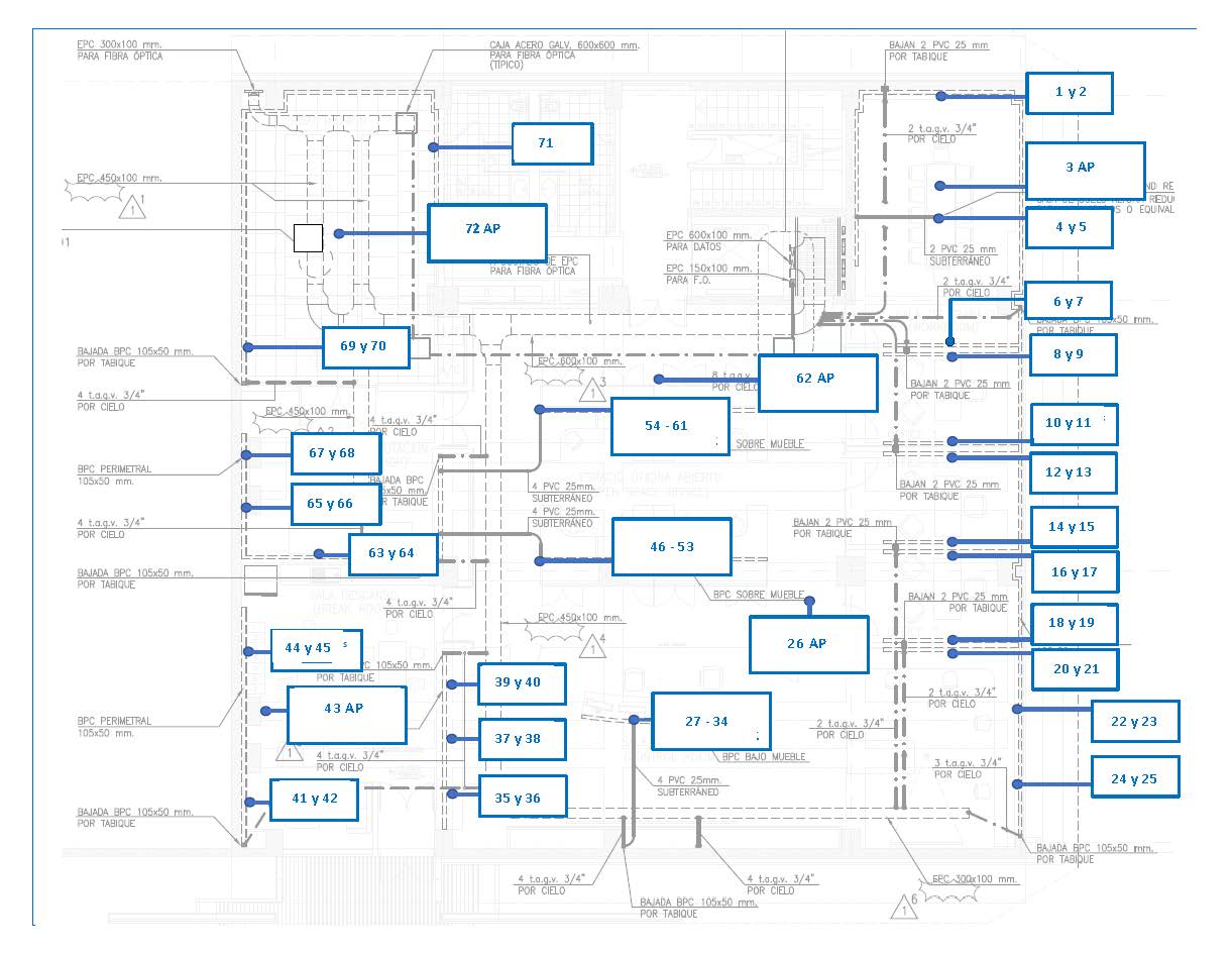
The second floor is made up of the following elements.
Second Floor:
- 72 Network points in total
- 5 Access points
- 3 24-port patch panel with modular jack, category 6A, 4 pairs
- 3 48-port switch
- 48U rack (A3)
This floor does not consider and optical terminal since the switches used are directly connected to the distribution switch. All of these connections are born from rack A3 located inside the main computer room.
In the following diagram, you can appreciate the various network points and the location of the rack with its connected components.
3.2.1 Second Floor
3.3 Third Floor
This floor is made up of 2 main connections, these connections feed the 2 sectors located in the third floor.
- Coating chamber
- Camera room (clean room and clean room)
- Level 3 Integration Lab (This is currently not set up with connectivity yet)
All of these connections are born from the computer room located in Rack A7 in the second floor of the main building. Rack A7 also provides connectivity to the rack found in the coating room and the rack found in the Camera room (Clean Room and White Room).
The third floor is made up of the following elements.
3.4 Coating Chamber
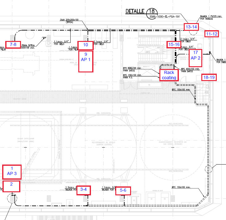
- 19 Network points in total
- 3 Access points
- 1 24-port patch panel with modular jack, category 6A, 4 pairs
- 1 Optic header with 12 Sm OS2 optical fibers and LC Full-Duplex UPC
- 24-port switch
- 1 6U wall rack
3.4.1 Coating Chamber Image
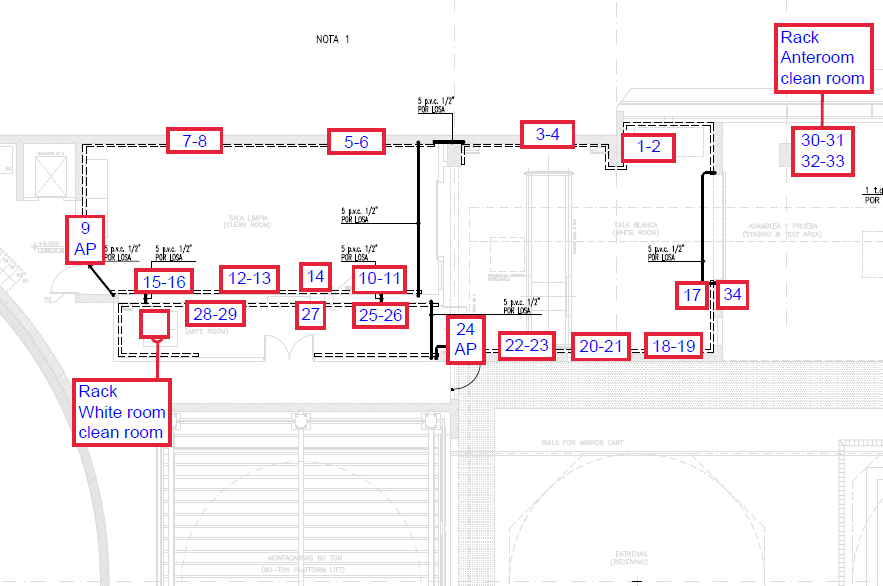
3.5 Camera Room
- 34 Network points in total
- 2 Access points
- 2 24-port patch panel with modular jack, category 6A, 4 pairs
- 1 Optic header with 12 Sm OS2 optical fibers and LC Full-Duplex UPC
- 24-port switch
- 1 48U rack
3.5.1 Camera Room Image
3.6 Fourth floor
There are currenlty no networking requirements for this floor.
3.7 Fifth floor
The fifth floor is made up of the following elements.
- 24 Network points in total
- 1 Access points
- 1 24-port patch panel with modular jack, category 6A, 4 pairs
- 1 Optic header with 12 Sm OS2 optical fibers and LC Full-Duplex UPC connectors
- 1 24-port switch
- 1 13U wall rack
In the following diagram illustrates the various network points and the location of the rack.
3.7.1 fifth-floor image
This rack is currently located in the electronics laboratory and has 24 fiber optic filaments that connect directly to rack A7 located in the main computer room on the second floor of the main building.
Please note, that all fiber optic connections on the various floors come from the second-floor computer room in rack A7. All the optical terminals from the various floors lead up to the optical headers of this rack.
4 Activities planned for FY21/22
4.1 Level 3 Integration Lab
Please note that a Level 3 test lab environment will be set up in the future as a workaround to solve any networking requirements for the dome or any other inquiries.
The materials contemplated for this lab enviroment are the following:
- 36 fiber-optic connections LC SM OS2 or 18 LC Full duplex ports SM OS2
- 36 fiber-optic connections LC MM OM3 or 18 LC Full duplex ports MM OM3
4.1.1 Level 3 Integration Lab Image
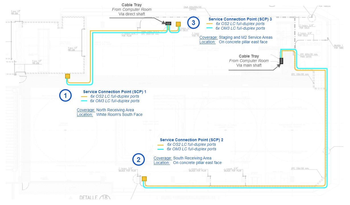
To build this lab environment, two types of optical fibers will be used (Single-Mode and Multi-Mode) as shown in the image above. This lab environment will also have an optical terminal on the main pillars of the building located in this area. Each of these terminals will have available 2 types of fiber optic connections, this will depend solely on the equipment connected to these pillars.
Deployment: FY21
In the near future, fiber optic connections will also be set up and installed on the 5th floor of the main building extending all the way up to where the dome is located.
4.2 96 Fiber Optic filament cable deployment
It is contemplated to have a 96 fiber optic filament cable that will be setup and installed in the second floor computer room wich will connect the upper floors of the building such as floor 5,6,7 and 8 and any other requirements that might arise.
Deployment 96 Fiber Optic Cable: FY21
4.2.1 Future Floor Image
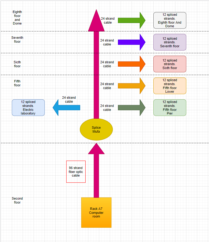
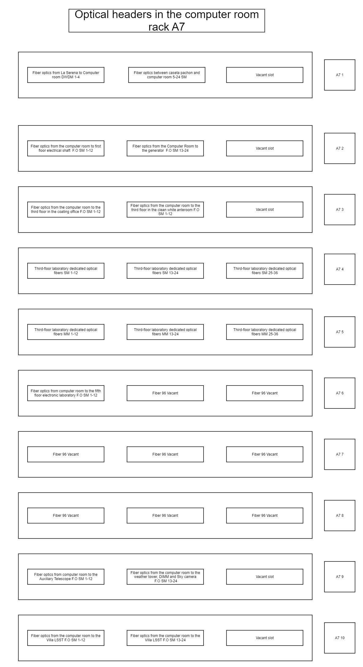
4.3 Fiber Headers
The image above illustrates a proposal of how the upper floors will look like in regard to the fiber optic connections on that floor.
Expected Deployment Date: FY21/23
4.4 Electronics Laboratory Fith floor
Based on the information provided above, this cable will replace the current connection that’s in place in the electronics laboratory and at the same time, this filament will connect to the Optical fiber splice enclosure (MUFA) located on that floor.
The idea of setting up and installing this connection arose from the fact that we currently haven’t gotten any requirements for the upper floors, and we feel that is necessary to be prepared for such requests in the future.
Expected Deployment Date: FY21
5 Acronyms
| Term | Meaning |
|---|---|
| 10G | 10 Gigabits |
| AP | Access Point |
| Auxtel | Auxiliary Telescope |
| AWG | American Wire Gauge |
| AURA | Associated Universities for Research in Astronomy |
| BDC | Base Data Center |
| CAT | Category |
| DWDM | Dense Wavelength Division Multiplexing |
| FY | Fiscal year |
| IEEE | Institute of Electrical and Electronics Engineers |
| IT | Information Technology |
| LAB | Laboratory |
| LC | Little Connector or Lucent Connector |
| LSZH | Low smoke zero halogen |
| MM | Multi-mode |
| MHZ | Megahertz |
| OM1 | Optical Multi-mode the number is the CAT of the cable |
| OM3 | Optical Multi-mode the number is the CAT of the cable |
| OS2 | Optical Single-mode the number is the CAT of the cable |
| S/FTP | Shielded/Foiled Twisted Pair |
| SM | Single-mode |
| TX | Transmission |
| UTP | Unshielded Twisted Pair |
| UPC | Ultra Physical Contact |
| UPS | Uninterruptible Power Supply |
| VoIP | Voice Over Internet Protocol |
| µm | Microns |
| nm | Nanometer |